

Appearance
Overexcitation Limiter (OEL2C)
IEEE 421.5 Type OEL2C overexcitation limiter: protects the generator field from thermal overload. The measured field current Ifd is scaled and filtered to Ipu; an inverse-time timer integrates K2*((Ipu/ITFpu)^c2 - 1) while the field is overloaded, and once it reaches TFCL the current reference Iref ramps from the instantaneous limit Iinst down to the thermal limit Ilim. The error Ibias + Iref - Iact drives a PID controller and two lead-lags whose limits make it a summation-point limiter (VOELmax = 0, lowers excitation only) or a take-over limiter (for an LV gate). Activation logic with pickup / reset delays keeps the limiter out of service in normal operation (Ibias = Ireset). Wire Ifd from the synchronous machine and VOEL to the exciter's VOEL input. Pairs with the machine for load-flow initialization.
Category: Control / Excitation
Overview
The Type OEL2C overexcitation limiter (IEEE Std 421.5-2016, clause 10.5) protects the generator field winding from thermal overload. A field winding can carry a high current for a short time (field forcing during a fault keeps the machine in step), but not indefinitely. OEL2C lets the voltage regulator force the field freely for a while, then — once an inverse-time "heating" timer expires — pulls the field current back down to its continuous rating.
The limiter outputs VOEL, a signal for the exciter's VOEL input. It does nothing in normal operation: VOEL sits at its resting value (0 for a summation-point limiter) until the field has been overloaded long enough.
Block diagram
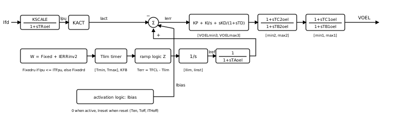
The model has four parts.
Measurement. The field current is scaled and filtered,
, and is what the limiter compares against its reference. Inverse-time timer. While the field is overloaded (
, the continuous rating) the timer integrates (with
in place of at or below the rating). With this is the classic heating model: twice the overload heats four times faster. The timer is limited to and, with , decays back on its own. Reference ramp. The current reference
rests at the instantaneous limit . Once the timer error reaches zero the reference ramps down to the thermal limit ; once the timer has recovered ( ) it ramps back up. The ramp rates are fixed ( , ) or follow the inverse-time term . Controller. The error
drives a PID controller and two lead-lag stages, each with its own output limits, producing VOEL.
Activation logic
The bias
Summation point or take-over
The standard sets the limiter's action through the output limits alone, and so does this component:
- Summation point (the default data):
and . VOEL is zero at rest and goes negative to lower excitation. Wire it to an exciter whose OEL input adds into the voltage error. - Take-over: a large
(e.g. 10). VOEL rests high and an LV gate in the exciter lets the limiter take control once VOEL drops below the regulator's own signal. Choose an exciter OEL location that uses a take-over gate.
Initialization
At the load-flow operating point the limiter is inactive: the reference rests at Ifd input. The first simulation step uses that seed in place of the input, so the limiter starts without a step.
Wiring
- Ifd ← the synchronous machine's
Ifdoutput. - VOEL → the exciter's
VOELinput (enable OEL input on the exciter's Aux Inputs tab and pick the location that matches the limiter's action).
Enable the monitors on the Monitoring tab to record VOEL, the reference Iref, the timer Tlim and the error Ierr.
Ports
| Port | Kind | Signal | Notes |
|---|---|---|---|
Ifd | Control input | Real | |
VOEL | Control output | Real |
Parameters
Pickup & Timer
| Parameter | Type | Default | Units | Description | ID |
|---|---|---|---|---|---|
| KSCALE | Number | 1 | — | Scaling factor applied to the measured field current before the transducer (pu). Use it to express Ifd in the limiter's own base. | KSCALE |
| TRoel | Number | 0.01 | s (also ms) | Field-current transducer time constant of KSCALE/(1+sTRoel). 0 senses directly. | TRoel |
| KACT | Number | 1 | — | Gain from the scaled current Ipu to the actual-current signal Iact compared against the reference. | KACT |
| ITFpu | Number | 3 | — | Continuous (thermal) field-current rating ITF in the scaled per-unit. Above it the inverse-time timer starts to integrate. | ITFpu |
| K1 | Number | 0 | — | Inverse-time gain of IERRinv1 = K1*((Ipu/ITFpu)^c1 - 1), the ramp rate used when the inverse-time ramp is selected. | K1 |
| c1 | Number | 0 | — | Exponent of the IERRinv1 inverse-time characteristic. | c1 |
| K2 | Number | 0.0296 | — | Inverse-time gain of IERRinv2 = K2*((Ipu/ITFpu)^c2 - 1), the rate at which the timer integrates during overexcitation. | K2 |
| c2 | Number | 2 | — | Exponent of the IERRinv2 inverse-time characteristic (2 gives the classic I^2 t heating model). | c2 |
| VINVmax | Number | 100 | — | Upper limit on IERRinv2. | VINVmax |
| VINVmin | Number | 0 | — | Lower limit on IERRinv2. 0 stops the timer from running backwards through this term. | VINVmin |
| Fixedru | Number | 0 | — | Fixed rate added to IERRinv2 while Ipu is at or below ITFpu (cooling side). | Fixedru |
| Fixedrd | Number | -0.001 | — | Fixed rate added to IERRinv2 while Ipu is above ITFpu (heating side). | Fixedrd |
| TFCL | Number | 10 | — | Timer threshold. Terr = TFCL - Tlim; the limiter acts once the timer Tlim reaches TFCL. | TFCL |
| Tmax | Number | 10 | — | Upper limit on the timer Tlim. | Tmax |
| Tmin | Number | 0 | — | Lower limit on the timer Tlim. | Tmin |
| KFB | Number | 0 | — | Timer self-reset feedback gain: the timer integrates W - KFB*Tlim. 0 makes the timer a pure integrator. | KFB |
Reference
| Parameter | Type | Default | Units | Description | ID |
|---|---|---|---|---|---|
| Iinst | Number | 6 | — | Instantaneous field-current limit: the reference Iref rests here while the timer has not expired (scaled pu). | Iinst |
| Ilim | Number | 3 | — | Thermal field-current limit: the reference ramps down to this level once the timer expires (scaled pu). | Ilim |
| TAoel | Number | 0.04 | s (also ms) | Reference filter time constant of 1/(1+sTAoel). 0 passes Iref straight through. | TAoel |
| SW1 | Choice: Fixed rates (KRU / KRD) / Inverse time (IERRinv1) | Fixed rates (KRU / KRD) | — | Ramp-rate selection: fixed rates KRU / KRD, or the inverse-time rate IERRinv1 for both directions. | SW1 |
| KZRU | Number | 0.99 | — | Ramp-up threshold factor: Iref ramps up once Terr >= KZRU*TFCL, ramps down once Terr <= 0, and holds in between. | KZRU |
| KRU | Number | 1000 | — | Fixed ramp-up rate of Iref (pu/s). | KRU |
| KRD | Number | -1000 | — | Fixed ramp-down rate of Iref (pu/s, negative). | KRD |
Activation
| Parameter | Type | Default | Units | Description | ID |
|---|---|---|---|---|---|
| Ireset | Number | 100 | — | Bias Ibias added to the error while the limiter is reset (inactive), so it cannot act. Ibias = 0 once active. | Ireset |
| Ten | Number | 0.2 | s (also ms) | Pickup delay: the limiter activates once Iact > Iref has held for Ten, or as soon as the timer expires. 0 keeps it always active. | Ten |
| Toff | Number | 5 | s (also ms) | Reset delay: the limiter resets once Iref is back at Iinst with Iref - Iact > ITHoff for Toff. | Toff |
| ITHoff | Number | 0.05 | — | Current margin below the reference required for the reset timer (scaled pu). | ITHoff |
Controller
| Parameter | Type | Default | Units | Description | ID |
|---|---|---|---|---|---|
| KPoel | Number | 0.3 | — | PID proportional gain. | KPoel |
| KIoel | Number | 1 | — | PID integral gain (non-windup integral). | KIoel |
| KDoel | Number | 0 | — | PID derivative gain of sKD/(1+sTD). | KDoel |
| TDoel | Number | 0.1 | s (also ms) | PID derivative filter time constant. | TDoel |
| VOELmax3 | Number | 0 | — | Upper limit of the PID output. 0 with a negative lower limit makes a summation-point limiter that can only lower excitation. | VOELmax3 |
| VOELmin3 | Number | -100 | — | Lower limit of the PID output. | VOELmin3 |
| TC2oel | Number | 0.1 | s (also ms) | Lead time constant of the second-stage lead-lag (1+sTC2oel)/(1+sTB2oel). Equal to TB2oel bypasses it. | TC2oel |
| TB2oel | Number | 0.1 | s (also ms) | Lag time constant of the second-stage lead-lag. | TB2oel |
| VOELmax2 | Number | 0 | — | Upper limit after the second-stage lead-lag. | VOELmax2 |
| VOELmin2 | Number | -100 | — | Lower limit after the second-stage lead-lag. | VOELmin2 |
| TC1oel | Number | 0.1 | s (also ms) | Lead time constant of the output lead-lag (1+sTC1oel)/(1+sTB1oel). Equal to TB1oel bypasses it. | TC1oel |
| TB1oel | Number | 0.1 | s (also ms) | Lag time constant of the output lead-lag. | TB1oel |
| VOELmax1 | Number | 0 | — | Upper limit of the output VOEL. 0 for a summation-point limiter; a large value (e.g. 10) for a take-over limiter feeding an LV gate. | VOELmax1 |
| VOELmin1 | Number | -10 | — | Lower limit of the output VOEL. | VOELmin1 |
Monitoring
| Parameter | Type | Default | Units | Description | ID |
|---|---|---|---|---|---|
| Monitor VOEL | Choice: Off / On | Off | — | Record the limiter output VOEL (pu) sent to the exciter's VOEL input as a named observable. | measure_voel |
| Monitor Iref | Choice: Off / On | Off | — | Record the field-current reference Iref (scaled pu), between Ilim and Iinst as a named observable. | measure_iref |
| Monitor Tlim | Choice: Off / On | Off | — | Record the inverse-time timer output Tlim; the limiter acts when it reaches TFCL as a named observable. | measure_tlim |
| Monitor Ierr | Choice: Off / On | Off | — | Record the error Ierr = Ibias + Iref - Iact (scaled pu) entering the PID as a named observable. | measure_ierr |
Signal Names
| Parameter | Type | Default | Units | Description | ID |
|---|---|---|---|---|---|
| VOEL name | Text | (empty) | — | Observable name for VOEL. Blank = skip. | voel_name |
| Iref name | Text | (empty) | — | Observable name for Iref. Blank = skip. | iref_name |
| Tlim name | Text | (empty) | — | Observable name for Tlim. Blank = skip. | tlim_name |
| Ierr name | Text | (empty) | — | Observable name for Ierr. Blank = skip. | ierr_name |
Initialization
| Parameter | Type | Default | Units | Description | ID |
|---|---|---|---|---|---|
| Ifd(0) | Number | 1 | — | Initial field current at t = 0 (pu). Seeds the transducer and stands in for Ifd on the first step. Normally set by the load-flow auto-initialization from the machine's field current. | ifd_init |
Observables
| Default name | Kind | Recorded when | Description | ID |
|---|---|---|---|---|
| set by VOEL name | Signal | Monitor VOEL is on | The limiter output VOEL (pu) sent to the exciter's VOEL input. | VOEL |
| set by Iref name | Signal | Monitor Iref is on | The field-current reference Iref (scaled pu), between Ilim and Iinst. | iref |
| set by Tlim name | Signal | Monitor Tlim is on | The inverse-time timer output Tlim; the limiter acts when it reaches TFCL. | tlim |
| set by Ierr name | Signal | Monitor Ierr is on | The error Ierr = Ibias + Iref - Iact (scaled pu) entering the PID. | ierr |