

Appearance
Power System Stabilizer (PSS2B)
IEEE 421.5 Type PSS2B dual-input power system stabilizer (the integral-of-accelerating-power stabilizer). The speed deviation (from the machine's speed output) and the electrical power Pe each pass two washouts and a transducer lag; the integrated power KS2/(1+sT7) is added to the speed signal, passed through a ramp-tracking filter [(1+sT8)/(1+sT9)^M]^N and subtracted again, which synthesizes an accelerating-power signal that does not respond to mechanical-power ramps. Gain KS1, three lead-lags and the [VSTMIN, VSTMAX] limit give VS for the exciter's VS input. The washouts keep VS = 0 in steady state. Wire speed and Pe from the synchronous machine. Pairs with the machine for load-flow initialization. Also known as PSS2A; equivalent to PSS2C with the fourth lead-lag and the output logic unused.
Category: Control / Excitation
Overview
The Type PSS2B power system stabilizer (IEEE Std 421.5) is the dual-input "integral of accelerating power" stabilizer, the most widely applied PSS structure. Like any stabilizer it adds damping torque to the electromechanical (0.1–2 Hz) rotor swings by modulating the voltage-regulator reference through VS.
A speed-only stabilizer (PSS1A) also reacts to genuine mechanical-power changes — a turbine ramp shows up as a speed deviation and the PSS fights it, swinging the terminal voltage. PSS2B instead synthesizes the accelerating power from speed and electrical power, then filters out the mechanical-power component with a ramp-tracking filter. The result responds to rotor swings but not to turbine ramps.
The 2016 edition of the standard supersedes PSS2B with PSS2C; PSS2B data is PSS2C data with the fourth lead-lag and the output logic unused, which is the structure implemented here.
Block diagram
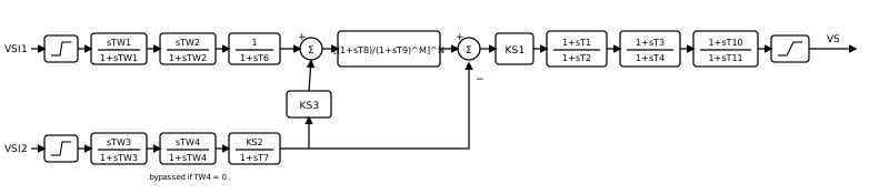
Block by block:
Speed channel. The speed deviation
(speed minus 1 pu), limited to , passes two washouts , and a transducer lag . Power channel. The electrical power, limited to
, passes the washouts and (bypassed when ), then . With this is the integral of electrical power expressed as a speed change. Accelerating power. The sum of the speed signal and
times the power signal is an estimate of the integral of mechanical power. The ramp-tracking filter removes torsional and noise content from it while tracking a ramp without steady error; subtracting the power signal again leaves the integral of accelerating power. Common choices are and ; bypasses the filter. Compensation and output. The gain
and three lead-lags , , provide the phase lead, and the output is limited to . Set a stage's lead and lag equal to bypass it.
Every washout bypasses itself when its time constant is 0, as the standard requires.
Initialization
All washouts remove the steady component, so VS = 0 at any steady operating point. The power-channel washout needs the machine's electrical power at
The machine's electrical outputs carry a short transient right after
Wiring
- speed (ω) ← the synchronous machine's
speedoutput (pu). - Pe ← the synchronous machine's
Peoutput (pu on the machine base). - VS → the exciter's
VSinput (enable PSS input on the exciter's Aux Inputs tab).
Enable the monitors on the Monitoring tab to record VS and the synthesized accelerating-power signal.
Tuning notes
- Pick
in the 2–10 s range and with the machine's inertia constant . - Tune the lead-lags for the phase lag of the exciter and field at the local-mode frequency, then raise
until the mode is well damped and back off for margin. - Keep the output band small (a few percent up, less down) so the stabilizer cannot dominate the regulator.
Ports
| Port | Kind | Signal | Notes |
|---|---|---|---|
speed | Control input | Real | |
Pe | Control input | Real | |
VS | Control output | Real |
Parameters
Inputs
| Parameter | Type | Default | Units | Description | ID |
|---|---|---|---|---|---|
| VSI1MAX | Number | 2 | — | Upper limit on the speed-deviation input VSI1 (pu). | VSI1MAX |
| VSI1MIN | Number | -2 | — | Lower limit on the speed-deviation input VSI1 (pu). | VSI1MIN |
| TW1 | Number | 10 | s (also ms) | Washout time constant of sTW1/(1+sTW1). 0 bypasses the washout. | TW1 |
| TW2 | Number | 10 | s (also ms) | Washout time constant of sTW2/(1+sTW2). 0 bypasses the washout. | TW2 |
| T6 | Number | 0 | s (also ms) | Transducer time constant 1/(1+sT6) of the speed channel. 0 bypasses it. | T6 |
| VSI2MAX | Number | 2 | — | Upper limit on the electrical-power input VSI2 (pu). | VSI2MAX |
| VSI2MIN | Number | -2 | — | Lower limit on the electrical-power input VSI2 (pu). | VSI2MIN |
| TW3 | Number | 10 | s (also ms) | Washout time constant of sTW3/(1+sTW3). 0 bypasses the washout. | TW3 |
| TW4 | Number | 0 | s (also ms) | Washout time constant of sTW4/(1+sTW4). 0 bypasses the washout. | TW4 |
| KS2 | Number | 1.43 | — | Gain of the power channel KS2/(1+sT7). For an integral-of-accelerating-power stabilizer KS2 = T7/(2H). | KS2 |
| T7 | Number | 10 | s (also ms) | Time constant of KS2/(1+sT7), which integrates the electrical power. Normally equal to TW2. | T7 |
| KS3 | Number | 1 | — | Gain of the power signal added ahead of the ramp-tracking filter. Normally 1. | KS3 |
Filter
| Parameter | Type | Default | Units | Description | ID |
|---|---|---|---|---|---|
| T8 | Number | 0.3 | s (also ms) | Lead time constant of the ramp-tracking filter [(1+sT8)/(1+sT9)^M]^N. | T8 |
| T9 | Number | 0.15 | s (also ms) | Lag time constant of the ramp-tracking filter. | T9 |
| M | Choice: 0 / 1 / 2 / 3 / 4 / 5 | 2 | — | Lag order M of the ramp-tracking filter (common: M = 5 with N = 1, or M = 2 with N = 4). | M |
| N | Choice: 0 / 1 / 2 / 3 / 4 | 4 | — | Number of cascaded ramp-tracking sections N. 0 bypasses the filter. | N |
Compensation
| Parameter | Type | Default | Units | Description | ID |
|---|---|---|---|---|---|
| KS1 | Number | 20 | — | Stabilizer gain applied after the ramp-tracking filter. | KS1 |
| T1 | Number | 0.16 | s (also ms) | First lead-lag lead time constant of (1+sT1)/(1+sT2). | T1 |
| T2 | Number | 0.02 | s (also ms) | First lead-lag lag time constant. | T2 |
| T3 | Number | 0.16 | s (also ms) | Second lead-lag lead time constant of (1+sT3)/(1+sT4). | T3 |
| T4 | Number | 0.02 | s (also ms) | Second lead-lag lag time constant. | T4 |
| T10 | Number | 1 | s (also ms) | Third lead-lag lead time constant of (1+sT10)/(1+sT11). Equal to T11 bypasses the stage. | T10 |
| T11 | Number | 1 | s (also ms) | Third lead-lag lag time constant. | T11 |
| VSTMAX | Number | 0.2 | — | Upper limit on the stabilizer output VS (pu). | VSTMAX |
| VSTMIN | Number | -0.066 | — | Lower limit on the stabilizer output VS (pu). | VSTMIN |
Monitoring
| Parameter | Type | Default | Units | Description | ID |
|---|---|---|---|---|---|
| Monitor VS | Choice: Off / On | Off | — | Record the stabilizer output VS (pu) sent to the exciter's VS input, after the [VSTMIN, VSTMAX] limit as a named observable. | measure_vs |
| Monitor accelerating power | Choice: Off / On | Off | — | Record the synthesized accelerating-power signal (pu) entering the KS1 gain: the ramp-tracking filter output minus the integrated electrical power as a named observable. | measure_vacc |
Signal Names
| Parameter | Type | Default | Units | Description | ID |
|---|---|---|---|---|---|
| VS name | Text | (empty) | — | Observable name for VS. Blank = skip. | vs_name |
| accelerating power name | Text | (empty) | — | Observable name for accelerating power. Blank = skip. | vacc_name |
Initialization
| Parameter | Type | Default | Units | Description | ID |
|---|---|---|---|---|---|
| Pe(0) | Number | 0 | — | Initial electrical power (pu on the machine base). Seeds the power-channel washout and stands in for Pe on the first step. Normally set by the load-flow auto-initialization. | p_init |
Observables
| Default name | Kind | Recorded when | Description | ID |
|---|---|---|---|---|
| set by VS name | Signal | Monitor VS is on | The stabilizer output VS (pu) sent to the exciter's VS input, after the [VSTMIN, VSTMAX] limit. | VS |
| set by accelerating power name | Signal | Monitor accelerating power is on | The synthesized accelerating-power signal (pu) entering the KS1 gain: the ramp-tracking filter output minus the integrated electrical power. | vacc |