

Appearance
Underexcitation Limiter (UEL2C)
IEEE 421.5 Type UEL2C underexcitation limiter: keeps the generator out of the underexcited region where it would lose steady-state stability or overheat the stator end. The active power PT, normalized to rated voltage by F1 = 1/u^K1 and filtered, sets the reactive-power limit Q' from a piecewise-linear P-Q characteristic (up to six segments); F2 = u^K2 scales it back to QREF. The error QREF - QT (times a fixed gain Kfix or the automatic gain Kadj) drives a PI controller and two lead-lags. While the machine stays inside its capability the error is negative, the integrator rests at VUImin and VUEL = 0. Wire Vt, Pe and Qe from the synchronous machine and VUEL to the exciter's VUEL input. Pairs with the machine for load-flow initialization.
Category: Control / Excitation
Overview
The Type UEL2C underexcitation limiter (IEEE Std 421.5-2016, clause 11.4) keeps a generator from absorbing more reactive power than it safely can. Run too far underexcited, a machine loses steady-state stability margin and overheats the stator end region. UEL2C compares the reactive power against a limit that depends on the active power and the terminal voltage, and raises the excitation through VUEL once the machine crosses that limit.
Inside the machine's capability the limiter is idle and VUEL = 0.
Block diagram
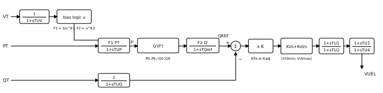
The model has four parts.
Voltage normalization. The filtered terminal voltage
passes a bias logic that gives : above 1 pu, between and 1 pu, and below . Setting disables the bias ( ). Then and . Limiting characteristic. The active power, normalized to rated voltage and filtered,
, indexes a piecewise-linear curve through up to seven points . Beyond the first and last points the end segments are extrapolated. The limit is scaled back to the actual voltage: . With the limit follows , like the machine's own steady-state stability limit. Error and gain. The error
is positive when the machine absorbs more than the limit allows. It is multiplied by a fixed gain , or by the automatic gain filtered by
, which reduces the loop gain at high active power. The automatic gain is kept between 0 and 1. Controller. A PI controller
limited to and two limited lead-lags produce VUEL.
Limits of this implementation
The standard's optional exciter-feedback term
Initialization
Inside the capability the error is negative, so the integrator rests on
The machine's electrical outputs carry a short transient right after
Wiring
- Vt, Pe, Qe ← the synchronous machine's
Vt,PeandQeoutputs (pu on the machine base, generator convention: Qe < 0 is absorbing). - VUEL → the exciter's
VUELinput (enable UEL input on the exciter's Aux Inputs tab).
Enable the monitors on the Monitoring tab to record VUEL, the limit QREF and the error VUerr.
Ports
| Port | Kind | Signal | Notes |
|---|---|---|---|
Vt | Control input | Real | |
Pe | Control input | Real | |
Qe | Control input | Real | |
VUEL | Control output | Real |
Parameters
Inputs
| Parameter | Type | Default | Units | Description | ID |
|---|---|---|---|---|---|
| TUV | Number | 5 | s (also ms) | Terminal-voltage filter time constant 1/(1+sTUV). | TUV |
| Vbias | Number | 1 | — | Voltage-bias threshold: u = VTF above 1 pu, u = 1 between Vbias and 1, u = VTF/Vbias below Vbias. Vbias = 1 disables the bias (u = VTF). | Vbias |
| K1 | Choice: 0 / 1 / 2 | 2 | — | Voltage exponent of F1 = 1/u^K1 that normalizes the active power to rated voltage. | K1 |
| K2 | Choice: 0 / 1 / 2 | 2 | — | Voltage exponent of F2 = u^K2 that scales the reactive limit back to the actual voltage. | K2 |
| TUP | Number | 5 | s (also ms) | Active-power filter time constant of F1*PT/(1+sTUP). | TUP |
| TUQ | Number | 0 | s (also ms) | Reactive-power filter time constant 1/(1+sTUQ). | TUQ |
| TQref | Number | 0 | s (also ms) | Reactive-reference filter time constant of F2*Q'/(1+sTQref). 0 passes it through. | TQref |
Characteristic
| Parameter | Type | Default | Units | Description | ID |
|---|---|---|---|---|---|
| Points | Choice: 2 / 3 / 4 / 5 / 6 / 7 | 5 | — | Number of points (P, Q) used to define the limiting characteristic (2 to 7, i.e. 1 to 6 segments). Beyond the first and last points the end segments are extrapolated. | n_points |
| P0 | Number | 0 | — | Active power of characteristic point 0 (pu on the machine base, normalized to rated voltage). Points must increase in P. | P0 |
| Q0 | Number | -0.31 | — | Reactive power of characteristic point 0 (pu, negative = absorbing). The limiter acts when the generator absorbs more than this. | Q0 |
| P1 | Number | 0.3 | — | Active power of characteristic point 1 (pu on the machine base, normalized to rated voltage). Points must increase in P. | P1 |
| Q1 | Number | -0.31 | — | Reactive power of characteristic point 1 (pu, negative = absorbing). The limiter acts when the generator absorbs more than this. | Q1 |
| P2 | Number | 0.6 | — | Active power of characteristic point 2 (pu on the machine base, normalized to rated voltage). Points must increase in P. | P2 |
| Q2 | Number | -0.28 | — | Reactive power of characteristic point 2 (pu, negative = absorbing). The limiter acts when the generator absorbs more than this. | Q2 |
| P3 | Number | 0.9 | — | Active power of characteristic point 3 (pu on the machine base, normalized to rated voltage). Points must increase in P. | P3 |
| Q3 | Number | -0.21 | — | Reactive power of characteristic point 3 (pu, negative = absorbing). The limiter acts when the generator absorbs more than this. | Q3 |
| P4 | Number | 1.02 | — | Active power of characteristic point 4 (pu on the machine base, normalized to rated voltage). Points must increase in P. | P4 |
| Q4 | Number | 0 | — | Reactive power of characteristic point 4 (pu, negative = absorbing). The limiter acts when the generator absorbs more than this. | Q4 |
| P5 | Number | 1.1 | — | Active power of characteristic point 5 (pu on the machine base, normalized to rated voltage). Points must increase in P. | P5 |
| Q5 | Number | 0.2 | — | Reactive power of characteristic point 5 (pu, negative = absorbing). The limiter acts when the generator absorbs more than this. | Q5 |
| P6 | Number | 1.2 | — | Active power of characteristic point 6 (pu on the machine base, normalized to rated voltage). Points must increase in P. | P6 |
| Q6 | Number | 0.4 | — | Reactive power of characteristic point 6 (pu, negative = absorbing). The limiter acts when the generator absorbs more than this. | Q6 |
Gain
| Parameter | Type | Default | Units | Description | ID |
|---|---|---|---|---|---|
| SW1 | Choice: Fixed gain Kfix (A) / Automatic gain Kadj (B) | Fixed gain Kfix (A) | — | Error gain: a fixed reduction Kfix (position A), or the automatic dispatch-dependent gain Kadj filtered by 1/(1+sTadj) (position B). | SW1 |
| Kfix | Number | 1 | — | Fixed gain applied to the error. 1 = no gain reduction. | Kfix |
| Tadj | Number | 3 | s (also ms) | Filter time constant of the automatic gain Kadj. | Tadj |
| Xq | Number | 1.8 | — | Machine quadrature-axis synchronous reactance used by Kadj = (VT^2/Xq + QT) / sqrt((VT^2/Xq + QT)^2 + PT^2) (pu). | Xq |
Controller
| Parameter | Type | Default | Units | Description | ID |
|---|---|---|---|---|---|
| KUL | Number | 0.8 | — | Proportional gain of the PI controller KUL + KUI/s. | KUL |
| KUI | Number | 0.5 | — | Integral gain of the PI controller (non-windup). | KUI |
| VUImax | Number | 0.25 | — | Upper limit of the PI output. | VUImax |
| VUImin | Number | 0 | — | Lower limit of the PI output. 0 keeps the limiter from acting outside its region. | VUImin |
| TU1 | Number | 0 | s (also ms) | Lead-lag time constant TU1 of the output stages (1+sTU1)/(1+sTU2) and (1+sTU3)/(1+sTU4). Equal lead and lag (or both 0) bypasses a stage. | TU1 |
| TU2 | Number | 0 | s (also ms) | Lead-lag time constant TU2 of the output stages (1+sTU1)/(1+sTU2) and (1+sTU3)/(1+sTU4). Equal lead and lag (or both 0) bypasses a stage. | TU2 |
| VUELmax2 | Number | 99 | — | Upper limit after the first lead-lag. | VUELmax2 |
| VUELmin2 | Number | -99 | — | Lower limit after the first lead-lag. | VUELmin2 |
| TU3 | Number | 0 | s (also ms) | Lead-lag time constant TU3 of the output stages (1+sTU1)/(1+sTU2) and (1+sTU3)/(1+sTU4). Equal lead and lag (or both 0) bypasses a stage. | TU3 |
| TU4 | Number | 0 | s (also ms) | Lead-lag time constant TU4 of the output stages (1+sTU1)/(1+sTU2) and (1+sTU3)/(1+sTU4). Equal lead and lag (or both 0) bypasses a stage. | TU4 |
| VUELmax1 | Number | 0.25 | — | Upper limit of the output VUEL. | VUELmax1 |
| VUELmin1 | Number | 0 | — | Lower limit of the output VUEL. 0 for a limiter that can only raise excitation. | VUELmin1 |
Monitoring
| Parameter | Type | Default | Units | Description | ID |
|---|---|---|---|---|---|
| Monitor VUEL | Choice: Off / On | Off | — | Record the limiter output VUEL (pu) sent to the exciter's VUEL input as a named observable. | measure_vuel |
| Monitor QREF | Choice: Off / On | Off | — | Record the reactive-power limit QREF (pu) the characteristic gives at the present P and V as a named observable. | measure_qref |
| Monitor VUerr | Choice: Off / On | Off | — | Record the error VUerr = QREF - QTF (pu); the limiter acts when it turns positive as a named observable. | measure_uerr |
Signal Names
| Parameter | Type | Default | Units | Description | ID |
|---|---|---|---|---|---|
| VUEL name | Text | (empty) | — | Observable name for VUEL. Blank = skip. | vuel_name |
| QREF name | Text | (empty) | — | Observable name for QREF. Blank = skip. | qref_name |
| VUerr name | Text | (empty) | — | Observable name for VUerr. Blank = skip. | uerr_name |
Initialization
| Parameter | Type | Default | Units | Description | ID |
|---|---|---|---|---|---|
| VT(0) | Number | 1 | — | Initial terminal-voltage magnitude (pu). Seeds the voltage filter and stands in for Vt on the first step. Normally set by the load-flow auto-initialization. | vt_init |
| PT(0) | Number | 0 | — | Initial active power (pu on the machine base). Seeds the P filter and stands in for PT on the first step. Normally set by the load-flow auto-initialization. | p_init |
| QT(0) | Number | 0 | — | Initial reactive power (pu on the machine base). Seeds the Q filters and stands in for QT on the first step. Normally set by the load-flow auto-initialization. | q_init |
Observables
| Default name | Kind | Recorded when | Description | ID |
|---|---|---|---|---|
| set by VUEL name | Signal | Monitor VUEL is on | The limiter output VUEL (pu) sent to the exciter's VUEL input. | VUEL |
| set by QREF name | Signal | Monitor QREF is on | The reactive-power limit QREF (pu) the characteristic gives at the present P and V. | qref |
| set by VUerr name | Signal | Monitor VUerr is on | The error VUerr = QREF - QTF (pu); the limiter acts when it turns positive. | uerr |