

Appearance
Turbine-Governor (HYGOV)
HYGOV hydro turbine-governor (IEEE PES-TR1), the hydro model most used in North American planning databases. It senses rotor speed ω and drives the synchronous machine's mechanical-torque input Tm. A mechanical-hydraulic governor with permanent droop R and temporary droop r: the speed error nref − Δω − R·c passes a filter 1/(1+sTf) and the governor (1+sTr)/(r·Tr·s), whose integrator is held to the gate velocity limit ±VELM and the position limits [GMIN, GMAX], giving the desired gate c; a servo 1/(1+sTg) moves the gate g. The nonlinear, inelastic water column gives the head h = (q/g)² and the flow TW·dq/dt = 1 − h, and the turbine delivers Pm = At·h·(q − qNL) − Dturb·g·Δω as torque Tm = Pm/ω. Opening the gate first drops the head, so the power dips before it rises: the non-minimum-phase response of a hydro unit. Pairs with the synchronous machine for bumpless load-flow initialization. The right-edge ω (in) and Tm (out) ports line up with the machine's left-edge speed (out) and Tm (in) ports for a direct connection.
Category: Control / Governor
Overview
The HYGOV turbine-governor models a hydro unit: a mechanical-hydraulic governor with permanent and temporary droop moving the wicket gate, and a nonlinear water column between the gate and the turbine. IEEE PES-TR1 describes it as its mechanical-hydraulic governor combined with the nonlinear inelastic water column, and names it among the hydro models most used in North American planning databases.
It senses the machine rotor speed ω and outputs the mechanical torque Tm that drives the machine. With the load-flow auto-initialization (below) the governor starts on its operating point, so a study begins in steady state with no torque transient.
The water column gives a hydro unit its signature response: when the gate opens, the water has to accelerate before more of it flows, so the head at the turbine first drops and the power dips before it rises. Steam and gas models cannot show this.
Block diagram
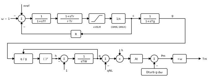
Signal flow, block by block (all quantities per-unit on the machine rating,
- Speed error and filter —
where
- Governor — the temporary-droop compensation
which is
Gate servo —
. Water column — with flow
and head at the turbine,
- Turbine power and torque —
A zero
Droop in terms of power
The power droop is therefore
The water column
Linearized around an operating point with flow
a right-half-plane zero: a gate step first moves the power the wrong way, by
The flow integrator is stepped implicitly, so the model stays stable as the gate closes and the water column's own time constant
Load-flow auto-initialization
After the load flow solves, the apply pass back-calculates the speed reference and the gate seed so every derivative in the diagram is zero at
- Pairing is wire-traced. The initializer follows the
Tmwire (throughGoTo/Fromlabels) to the unique synchronous machine whoseTmit feeds. Fan-out to several machines skips initialization with a warning. - The gate holds the machine's power at rated head. With the water column at rest the head is 1 and the flow equals the gate, so
with
A warning is raised, and the seed still proposed, when
These quantities populate nref and g(0) on the Initialization tab. On the first time step the model uses
Wiring
- ω ← the synchronous machine's
speedoutput. - Tm → the synchronous machine's
Tminput.
Enable Monitor Pm / gate / head on the Monitoring tab to record the mechanical power, the gate opening and the turbine head.
When to use something else
- A steam unit: use IEEEG1 (or the minimal TGOV1).
- A gas turbine or a governor with load and acceleration limiters: use GGOV1.
Ports
| Name | Direction | Value type | Notes |
|---|---|---|---|
speed | input | double | |
Tm | output | double |
Parameters
Governor
| Name | Label | Type | Default | Units | Description |
|---|---|---|---|---|---|
R | R (permanent droop) | double | 0.05 | — | Permanent droop (pu gate per pu speed): in steady state a speed drop Δω opens the gate by Δω/R, so the mechanical power rises by about At·Δω/R. R = 0 makes the governor isochronous: it returns the speed to its reference. |
rtemp | r (temporary droop) | double | 0.3 | — | Temporary droop r (pu): the governor's transient gain is 1/r, much lower than the steady 1/R, so the gate does not chase the water column's fast dynamics. With r = 0 (or Tr = 0) the gain is unbounded and the gate moves at the velocity limit. |
Tr | Tr | double | 5 | s (s, ms) | Governor reset (dashpot) time constant: the temporary droop washes out with Tr, leaving the permanent droop R. |
Tf | Tf | double | 0.05 | s (s, ms) | Filter (pilot valve) time constant on the speed error. 0 bypasses the filter. |
Tg | Tg | double | 0.5 | s (s, ms) | Gate servo time constant. 0 bypasses the servo, so the gate follows the desired gate c directly. |
VELM | VELM | double | 0.2 | — | Gate velocity limit (pu/s), the reciprocal of the time the gate takes to travel from fully open to fully closed. Applies to opening and closing alike; read as its magnitude. |
GMAX | GMAX | double | 1 | — | Maximum gate opening (pu): the gate limit set at the governor, at most 1. Non-windup upper limit on the desired gate c. |
GMIN | GMIN | double | 0 | — | Minimum gate opening (pu), normally 0. Non-windup lower limit on the desired gate c. |
Turbine
| Name | Label | Type | Default | Units | Description |
|---|---|---|---|---|---|
TW | TW | double | 1 | s (s, ms) | Water starting time at rated flow and head: the time the head needs to accelerate the water column to rated flow. A larger TW gives a deeper initial power dip. 0 drops the water column, so the flow equals the gate and the head stays at 1. |
At | At (turbine gain) | double | 1.2 | — | Turbine gain, 1/(gFL − gNL) for the full-load and no-load gate openings gFL and gNL: converts flow above the no-load flow into power on the machine rating. |
Dturb | Dturb | double | 0 | — | Turbine damping (pu on the machine rating): subtracts Dturb·g·Δω from the mechanical power, the turbine's own self-regulation against speed. 0 leaves damping to the machine and the network. |
qNL | qNL (no-load flow) | double | 0.08 | — | No-load flow (pu of rated flow): the flow that spins the unloaded unit at rated speed, covering the turbine's fixed losses. |
Monitoring
| Name | Label | Type | Default | Units | Description |
|---|---|---|---|---|---|
measure_pmech | Monitor Pm | enum (Off / On) | 0 | — | Record the turbine mechanical power Pm (pu) as a named observable. |
measure_gate | Monitor gate | enum (Off / On) | 0 | — | Record the gate opening g (pu) as a named observable. |
measure_head | Monitor head | enum (Off / On) | 0 | — | Record the turbine head h (pu) as a named observable. |
Signal Names
| Name | Label | Type | Default | Units | Description |
|---|---|---|---|---|---|
pmech_name | Pm name | string | (empty) | — | Observable name for the mechanical power Pm. Blank = skip. |
gate_name | Gate name | string | (empty) | — | Observable name for the gate opening g. Blank = skip. |
head_name | Head name | string | (empty) | — | Observable name for the turbine head h. Blank = skip. |
Initialization
| Name | Label | Type | Default | Units | Description |
|---|---|---|---|---|---|
pref0 | nref | double | 0 | — | Speed reference nref (pu): R·g(0), the value that balances the permanent droop at synchronous speed. Normally computed by the load-flow auto-initialization so the governor starts in balance; set manually only for standalone use. |
gate0 | g(0) | double | 0 | — | Initial gate opening at t = 0 (pu), Pm(0)/At + qNL at rated head. Seeds the desired gate, the gate and the flow (equal to the gate at rated head). Normally set by the load-flow auto-initialization from the paired machine's operating point. |
Observables
| Signal | Type | Default name | Enable | Description |
|---|---|---|---|---|
pmech | signal | from pmech_name | measure_pmech | Turbine mechanical power Pm (pu): At·h·(q − qNL) − Dturb·g·Δω. |
gate | signal | from gate_name | measure_gate | Gate opening g (pu), the servo output. |
head | signal | from head_name | measure_head | Turbine head h = (q/g)² (pu of rated head); it dips below 1 while the water column accelerates after the gate opens. |